Hello again! Welcome back to this series – we’re discussing a systems engineering process that could have prevented a massive change control in one of my previous lives. In the previous post, we discussed that defining and understanding use cases identifies the scope and boundary of a project. Now, we’re going to talk about how a use case analysis can inform your design. We typically think about use case analyses as way to define top level system behavioral requirements, but in this specific case, the ultimate goal is to define all potential equipment in a laboratory that would consume power. (If you remember - a lab was unusable because of an insufficient power supply due to poor planning and communication at the inception of the project.)
In the aforementioned post, we identified use cases to describe the expected (and future) functionality in a Cell Lab. In a traditional use case analysis, use cases are decomposed to describe the actual behavior the system performs as a result of user interactions and the main goal is to determine the system’s behavioral requirements.
In this example, I decomposed each use case to create a draft order of events and assumed operational flow of the user activities. Notice how ‘draft’ is in bold. This is super important! I was not the SME. When it comes to use case analyses (and many other analyses), it’s important that we never move to the next step using assumptions. (In some cases, we have to, but we should always clearly state our assumptions and ensure we address them at a later point.)
If we are trying to reach a conclusion or decision about something, it's a great idea to present a potential solutions (with assumptions ) to the larger group. I have found that people are much more likely to give more information, comments, details, you name it, if they are provided with a baseline to start their thought process. In my case, I presented my assumption of the internal processes in the laboratory in order to receive constructive, detailed feedback that I could use to update the use case analysis.
As Systems Engineers, we are the glue the holds everything together. It's our job to understand the facts. Never assume. Assumptions result in failure. We must practice emotionally detaching ourselves from our work. Our job is to collect, understand, and process facts, not to be right the first time around.
I used activity diagrams to decompose the use cases, however, we could also use state machines, interactions, or many other non SysML methods to perform a use case analysis. The activity diagrams display the order of operations of the user; the names of the actions on the diagrams start with a verb in the context of the operator. By analyzing each use case to understand the action or activities the user performs, I can identify gaps in ‘user needs.’ I can also use this work as a baseline to understand human factors in system and process development.
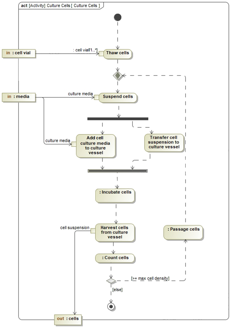
The specific use case that is decomposed into an activity diagram is Culture Cells from this blog post. Culture Cells has an extending use case, Passage Cells, and included use case, Prepare Culture Media. The Culture Cells use case analysis resulted in the activity diagram displayed in Figure 1.

The activity starts by thawing cells, which consumes cell vials. The number of cell vials could be as few as 1 or as many as needed (indicated by ‘1..*’.) After thawing cells, the user suspends cells in culture media, then adds both the culture media and cell suspension to a culture vessel. The fork node (black bar) splits the path – both Add cell culture media to culture vessel and Transfer cell suspension to culture vessel must happen before the operator can Incubate cells, hence the join node before the Incubate cells call behavior action. After the operator Incubates cells, they Harvest cells from culture vessel, and Count cells. A decision will be made whether to Passage cells or complete the Culture Cells activity based on the cell density of the suspension.
It's important to recognize each of these process steps in order to perform an additional analysis to determine the type and quantity of equipment. It’s also important to understand how each process step is currently performed as well as potential process improvements. That will enable future-proofing the laboratory circuits to ensure there will always be a sufficient power supply and give insight into future budgeting exercises (for equipment and resources.) Watch for the next post, where I will show some useful systems engineering diagrams that I like to use for equipment and material identification.

%20copy%202.png)